Step 7 Modbus TCP: ET 200SP with Altivar VFD

regeditor

Level-1
Beiträge
28
Reaktionspunkte
1
Zuviel Werbung?
-> Hier kostenlos registrieren
Hello,

It is intended to control a Schneider Variable Frequency Drive (VFD): ATV630U30N4 via Siemens PLC: ET 200SP, using Modbus TCP communication protocol. The VFD has a built-in Ethernet adapter which can be used for Modbus TCP communication.

I have connected the VFD as well as the ET 200SP to an ethernet switch, using STP CAT5 LAN cables, and assigned to them the following IP configurations:

VFD: 192.168.50.155

PLC: 192.168.50.156

From my host computer, I can ping both the PLC as well as the VFD and receive a reply. Moreover, I can access to the VFD's webserver and read/write different configurational parameters, where also I can "blink LED" on the PLC, using PRONETA. At this level, the connection criteria is established.

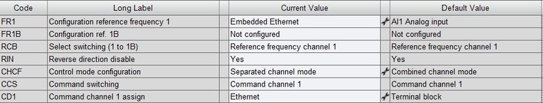
For the VFD parametrization, I have configured it using the SoMove software (a GUI for the VFD configuration from Schneider Electric), aside than the intrinsic IP assignment, as follows:

Configuration reference frequency : Embedded Ethernet (the default value is AI1 Analog input)

Control mode configuration : I/O mode (the default value is Combined channel mode)

Command channel 1 assign : Ethernet (the default value is Terminal block)

According to what have been precedent, the VFD is set to receive the reference frequency via Modbus TCP, where the value for the latent is to be sent (written) from the PLC.

Using TIA PORTAL V17, I have created a new project in which the PLC is configured (eg, the PROFINET address is set to 192.168.50.156, Simulation is supported, etc.). I have used the system instruction "MB_CLIENT" of version 4.1, and created a global DB, labeled as "MB_Client_Config" and set as attached.

I have created a global DB, labeled as "Modbus_Master_Write_DB", in which I have created the frequency tag to be written to the VFD, with its data type as "USInt". As a reminder, the target at this level is to only send the reference frequency to the VFD, where I can see it on its embedded LCD. To be noted that, I can change the reference frequency using SoMove on the host PC and see its reflection on the VFD's LCD, therefore, no communication problems.

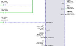
Attached in two figures is the instruction with its I/O parameters. Concerning the values of MB_MODE, MB_DATA_ADDR, and MB_DATA_LEN they are set as follows:

MB_MODE = 1 (because I want to write one holding register)

MB_DATA_ADDR = 8502 (this is the logical address of the reference frequency holding register as attached and highlighted in yellow)

MB_DATA_LEN = 1

When I log online into the PLC, the instruction does NOT work as supposed to: on the STATUS I keep seeing rapidly fluctuating values of 7005 , 7006 , 8381

Can you please help me identifying and solving the cause of the problem?
 

Anhänge

  • MB_Client_Config.jpg
    MB_Client_Config.jpg
    113,1 KB · Aufrufe: 18
  • logical address.jpg
    logical address.jpg
    43,4 KB · Aufrufe: 18
  • FB1.jpg
    FB1.jpg
    57 KB · Aufrufe: 18
  • FB2.jpg
    FB2.jpg
    27,6 KB · Aufrufe: 14
Hi

try this parameter combinations:
MB_MODE = 1
MB_DATA_ADDR = 48503 //register number + 40001 e.g.: 8502 + 40001 = 48503
MB_DATA_LEN = 1

or

MB_MODE = 106
MB_DATA_ADDR = 8502 //register number
MB_DATA_LEN = 1

see TIA Help for MB_CLIENT, "Parameters MB_MODE, MB_DATA_ADDR and MB_DATA_LEN" for Modbus-Function 06

Harald
 
Zuviel Werbung?
-> Hier kostenlos registrieren
Hi

try this parameter combinations:
MB_MODE = 1
MB_DATA_ADDR = 48503 //register number + 40001 e.g.: 8502 + 40001 = 48503
MB_DATA_LEN = 1

or

MB_MODE = 106
MB_DATA_ADDR = 8502 //register number
MB_DATA_LEN = 1

see TIA Help for MB_CLIENT, "Parameters MB_MODE, MB_DATA_ADDR and MB_DATA_LEN" for Modbus-Function 06

Harald
Thank you for your help!

I previously have tried your suggestions. But still, none did work!

For

/MB_MODE = 1
MB_DATA_ADDR = 48503
MB_DATA_LEN = 1/ : the ERROR bit is TRUE and the STATUS is 16#8383

For

/MB_MODE = 106
MB_DATA_ADDR = 8502 //register number
MB_DATA_LEN = 1/ : the ERROR bit is also TRUE with the same STATUS as 16#8383
 

Anhänge

  • error1.jpg
    error1.jpg
    45,5 KB · Aufrufe: 10
  • error2.jpg
    error2.jpg
    46,5 KB · Aufrufe: 8
STATUS 16#8383 : MB_DATA_PTR is wrong
see TIA Help for MB_CLIENT, "Parameter STATUS"

What is the data type of "Modbus_Master_Write_DB"."Frequency Write"? What is the value of the Variable?
Data type should be INT (signed 16 Bit) and the value in the range of -5000...+5000


The ATV630 use a Modbus-ID or Modbus-address?
If the device have a Modbus-ID <> 255, then you must set the instance variable MB_Unit_ID to the same ID that the device use.
see TIA Help for MB_CLIENT for MB_Unit_ID

Do you have a ModbusTCP Test-Client App? Can you communicate with this Test-Client with the VFD?

Harald
 
You need to configure Modbus, cant write directly to the Registers with this method.
This is how I communicate with 3xx, 6xx and 9xx, examples written out of my 6xx ATV-FB (can't give the whole thing out, sorry)

Control mode configuration : I/O mode (the default value is Combined channel mode)
My ATV6xx-FB requires this to be set to "Separated channel mode"
In Parameters List->Fieldbus
->Generic Setings set "Swap Word order" to "ModBux Word Order OFF"
-> Protocol & Drive Profiles must be set correct. Iam telling the VFD here what I want to communicate:
1666604162811.png


Write to Drive:
Mode 116
Len 2
Addr 0

PTR-UDT here:
Code:
CMD    Word
LFRD    Int

My config for CMD:
Initialize: w#16#0007
Start right: w#16#000f
Reset Error: w#16#0080
Stop: w#16#0006

Reading:
Mode 103
Len 16
Addr 0

For PTR I use UDTs:
Code:
ETA    Word
RFRD    Int
AIV1    Int
STOS    Word
HMIS    Word
LFT    Word
THD    UInt
THR    UInt
RTH    UInt
PTH    UInt
ULN    UInt
RFR    Int
OTR    Int
LCR    UInt
UOP    UInt
OPR    Int
 
Zuviel Werbung?
-> Hier kostenlos registrieren
What is the data type of "Modbus_Master_Write_DB"."Frequency Write"? What is the value of the variable?
Data type should be INT (signed 16 bit) and the value in the range of -5000...+5000


If the device have a Modbus ID <> 255, then you must set the instance variable MB_Unit_ID to the same ID that the device use.
see TIA Help for MB_CLIENT for MB_Unit_ID

Do you have a ModbusTCP Test Client App? Can you communicate with this test client with the VFD?

Harold
Hi Harold, and thanks again.

As for the data type of: "Modbus_Master_Write_DB"."Frequency Write" it is of USint and its value is "50" (ie, I want the reference frequency to be of 50Hz).

The VFD is communicated through via Modbus TCP. I can test/debug it using its "Test Client App" which is SoMove. I can set the desired reference frequency using that App and see its reflection on the VFD's embedded LCD without any problem.
 
Zuviel Werbung?
-> Hier kostenlos registrieren
You need to configure Modbus, can't write directly to the Registers with this method.
This is how I communicate with 3xx, 6xx and 9xx, examples written out of my 6xx ATV-FB (can't give the whole thing out, sorry)


My ATV6xx-FB requires this to be set to "Separated channel mode"
In Parameters List->Fieldbus
->Generic Settings set "Swap Word order" to "ModBux Word Order OFF"
-> Protocol & Drive Profiles must be set correct. I am telling the VFD here what I want to communicate:
Anhang anzeigen 64460


Write to Drive:
fashion 116
len 2
addr 0

PTR UDT here:
Code:
CMD Word
LFRD Int

My config for CMD:
Initialize: w#16#0007
Start right: w#16#000f
Reset Error: w#16#0080
Stop: w#16#0006

Reading:
fashion 103
len 16
addr 0

For PTR I use UDTs:
Code:
ETA Word
RFRD Int
AIV1 Int
STOS Word
HMIS Word
LFT Word
THD UInt
THR UInt
RTH UInt
PTH UInt
ULN UInt
RFR Int
OTR Int
LCR UInt
UOP UInt
OPR Int
Many thanks!

So I believe that your ATV_FB is something different than a regular MB_Client FB? Or you just use the MB_Client with a code addition to change different I/O parameters of the block?
 
My ATV_FB is using the MB_Client but specialized for ATVs address-table and behavior.
When using 200 drives in one project You need an FB for copy&paste :D.


I can take this as U managed to operate Your VFD?
Thank you for your interest.

Not really. I'm still trying. I have made all the Configs needed for the VFD in SoMove as you have told.

Still, I need to check it via TIA FB. I have changed the CPU to 1515-2PN.

I will acknowledge back all results.

Thanks again
 
Zuviel Werbung?
-> Hier kostenlos registrieren
I can take this as U managed to operate Your VFD?
As a side note,

I have set the IP address for the new CPU via PRONETA and it is now (in addition to the VFD) pingable from the host computer.

When I attempt to download the project, it reveals that the destination PLC is not reachable!

Any comments please?
 
Zuviel Werbung?
-> Hier kostenlos registrieren
I would try to perform the online-diagnosis on the adapter in the left menulist, maybe the IP was set but profinet name is wrong, then TIA sometimes stops connecting thinking its a wrong device. If so, use the netview for the devices to assign IP+name instead of proneta.
 
I would try to perform the online diagnosis on the adapter in the left menu list, maybe the IP was set but profinet name is wrong, then TIA sometimes stops connecting thinking its a wrong device. If so, use the netview for the devices to assign IP+name instead of proneta.
I am unable to change the device name in PRONETA!

Regardless, I have tried to adjust the CPU name the same as in PRONETA but still the device is NOT reachable (present in the list of target devices but cannot connect)
 
Zuviel Werbung?
-> Hier kostenlos registrieren
You should try to do a factory reset and then load again but in TIA.
Thank you!

I have attempted to physically reset the PLC to factory settings, where still, after seeing it in PRONETA, its name is not changeable (as attached). I do not have any access to the PLC in TIA, since its IP address is showing unreachable, and therefore not a single online connection was established with the PLC.
 

Anhänge

  • Screenshot 2022-10-25 084749.jpg
    Screenshot 2022-10-25 084749.jpg
    13,1 KB · Aufrufe: 5
If the plc is blank on factory settings then TIA Portal must find it via the first try on downloading. Then it should attempt to assign an ip temporarily for Your network-adapter and download hardware-config and the program itself.

I've never even installed proneta, so I can't tell what its doing. Everything I need to do is done within TIA.
Hi again!

I now have the 1515-2PN loaded with the MB_Client FB (the connection criteria between the PLC and the VFD is well established). Concerning SoMove configurations, attached it is what have been changed.

The purpose is to only send the LFR (logical address = 8502) value from the MB_Client in the PLC. Unfortunately, I keep receiving the same output as initially!

Any further help would also be greatly appreciated.
 

Anhänge

  • Screenshot 2022-10-25 193451.jpg
    Screenshot 2022-10-25 193451.jpg
    59 KB · Aufrufe: 12
  • Screenshot 2022-10-25 193510.jpg
    Screenshot 2022-10-25 193510.jpg
    45,4 KB · Aufrufe: 12
  • Screenshot 2022-10-25 193525.jpg
    Screenshot 2022-10-25 193525.jpg
    65,4 KB · Aufrufe: 12
Zurück
Oben